Electrical Design for Consumer Products: A Complete Guide
A consumer electronics concept can look simple from the outside, yet its electrical system must satisfy tight limits for size, performance, safety, cost, and manufacturability. Decisions made before the first prototype, from charge-current limits to battery targets and available internal volume, shape every downstream design choice.
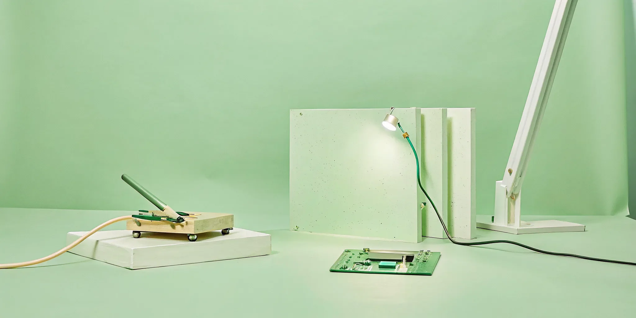
Electrical design for consumer products is the process of defining functional requirements, developing and integrating the circuitry and PCB. Selecting components, building and testing prototypes, and preparing the validated design for reliable, compliant manufacturing.
The work is not limited to drawing a schematic. It connects user needs to power architecture, physical packaging, thermal behavior, compliance requirements, and production realities. A successful process turns those constraints into a product that performs consistently in the hands of real customers. Start by clarifying what the electrical system must do, how much space it can occupy. And which performance targets matter most, then use those requirements to guide the design from the first block diagram through manufacturing.
Book a call to discuss your consumer product’s electrical design requirements.What Is Electrical Design for Consumer Products?
Electrical design for consumer products defines how a product receives, distributes, controls, and uses electrical power. It includes functional requirements, circuit design, component selection, PCB layout, and system-level architecture. The work must fit the product's physical envelope while delivering dependable performance, safe operation, and a practical path from prototype to manufacturing.
More Than a Circuit Diagram
Electrical design begins by translating the product experience into measurable requirements. A connected device, portable charger, wellness product, or household appliance may need defined limits for input voltage. Charge current, battery state of charge, output power, operating temperature, and standby consumption. For example, one consumer-device specification establishes automatic USB charge-current limiting at 1.0 amp and a maximum output of 2.7 amps. These requirements give the design team clear boundaries for selecting components and validating performance.
From there, the work spans several connected layers:
Circuit design: Defining power conversion, protection, sensing, charging, and signal paths.
PCB layout: Arranging components and traces so the board supports current loads, signal integrity, thermal behavior, and assembly.
System architecture: Connecting the power system, processor, sensors, user interface, wireless functions, battery, and other subsystems into one coherent product.
Designing Within Real Product Constraints
Consumer products rarely offer unlimited space. The enclosure, battery, display, controls, connectors, and other mechanical elements compete for the same volume. A referenced portable-device specification sets a maximum volume of 200 cm3, illustrating how a size constraint can shape the electrical architecture from the start. Electrical and industrial design decisions therefore need to develop together, rather than treating the PCB as an isolated part.
Safety Is a Core Requirement
Performance alone is not enough for a product intended for consumers. The U.S. Consumer Product Safety Commission states that manufacturers are responsible for ensuring their products are safe and comply with applicable safety standards. That responsibility affects circuit protection, charging behavior, insulation, enclosure interfaces, testing, and documentation. Safety compliance should be considered during architecture and prototyping, not added as a final checkpoint. Jackson Hedden combines electrical design with broader industrial design services to help teams resolve these technical and physical requirements as one manufacturable product.
Sources:University of Illinois ECE project requirements; U.S. Consumer Product Safety Commission guidance.
Key Stages of the Electrical Design Process
The electrical design process for a consumer product moves from functional requirements to a validated, manufacturable system. Teams define what the product must do, translate those requirements into circuit architecture, simulate and lay out the design, then build prototypes for testing. Each stage reduces technical risk before production investment increases.
Define requirements and functional modules
Start by documenting the product's electrical and physical constraints. Requirements may include charge-current limits, battery state-of-charge targets, voltage ranges, operating conditions, dimensions, and user-facing performance goals. At this stage, a high-level block diagram breaks the product into manageable functional modules, such as power input, regulation, charging, control, sensing, and output. This shared architecture gives industrial design, electrical design, firmware, and manufacturing teams a clear basis for decisions. The requirements should be specific enough to test later, while remaining aligned with the product experience and enclosure constraints. A connected device may also benefit from the broader connected consumer product design process.
Develop the schematic
Once the architecture is established, the team converts each functional block into a detailed schematic. This includes selecting circuit topologies, defining signal and power paths, specifying interfaces, and identifying components that can meet the requirements. The schematic should also make design intent and key assumptions visible to reviewers. Early documentation helps expose missing protections, incompatible interfaces, or requirements that cannot be met within the available space, power budget, or cost target.
Simulate circuit behavior
Simulation provides an opportunity to evaluate circuit behavior before committing to a physical board. For example, LTSpice simulations can help predict voltage response, regulation behavior, transient performance, and likely component stress in a power circuit. Simulation does not replace physical testing, but it can identify unstable designs and refine component values before fabrication. The prototype-to-PCB workflow commonly progresses from detailed schematics to LTSpice analysis and then to board layout, as demonstrated in the Cal Poly power-converter design reference.
Complete the PCB layout
After the schematic and simulation results are reviewed, the design is translated into a board layout. Component placement, trace routing, grounding, clearance, thermal paths, and mechanical interfaces all matter. Layout decisions must account for expected current loads and sensitive signals, not just whether the board fits its nominal outline. Coordination with the enclosure and industrial design is essential when the product has strict volume or access constraints.
Build and refine the prototype
The first physical build connects the electrical design to real components, manufacturing tolerances, and the intended product form. Teams should maintain a current bill of materials, revision history, and build notes so each prototype can be reproduced and compared. Prototype findings may require component substitutions, a PCB revision, changes to the enclosure, or updates to the requirements.
Test against requirements
Testing validates electrical performance under expected operating conditions and identifies problems that simulation could not reveal. Measure relevant voltages, current draw, temperature, interfaces, and functional behavior, then compare the results with the original requirements and simulated predictions. The build-test-troubleshoot cycle is iterative. Documented results create the evidence needed to improve the design, prepare for compliance work, and make a controlled transition toward manufacturing.
PCB Design and Component Selection for Consumer Electronics
Effective PCB design for consumer electronics balances signal integrity, thermal performance, power efficiency, and physical constraints. A sound layout separates noisy power-conversion paths from sensitive circuits, selects regulators for the required load and efficiency, and sizes traces to carry current safely. These decisions make the product more reliable, manufacturable, and easier to refine.
PCB decisions should follow the product's functional requirements, enclosure geometry, operating environment, and expected production volume. Teams developing embedded product design should treat the board as part of the complete product architecture, not as an isolated electrical deliverable.
Use the layer stack to control noise and heat
Power converters can create switching noise that interferes with sensors, wireless radios, audio paths, and other sensitive circuits. A deliberate layer strategy keeps high-current and high-frequency loops compact, provides dependable return paths, and places sensitive components away from noisy switching nodes. Effective power-converter layouts also use distinct top and bottom layers where appropriate to support component placement. Routing, and thermal performance, as demonstrated in Cal Poly's power-electronics design documentation (source).
Layer planning must also account for the enclosure. A compact board may need to fit around batteries, fasteners, displays, or mechanical features, while heat-generating components need a practical path into copper areas or other dissipation features. Resolving these constraints early reduces late-stage board reshuffling and enclosure changes.
Select components for the complete power architecture
Component selection is more than matching an input and output voltage. The design team should evaluate load range, conversion efficiency, quiescent current, transient response, package size, thermal limits, availability, and lifecycle risk. The right power management integrated circuits, buck converters, and linear regulators help balance efficiency, noise, cost, and longevity. In some circuits, an efficient switching regulator is appropriate for larger voltage conversion, while a low-noise linear regulator may be better for a sensitive downstream rail. Cal Poly's reference design identifies LDO selection and buck-converter implementation as central power-design decisions (source).
Route traces for current, heat, and serviceability
Trace width, copper thickness, via strategy, and routing length should reflect expected current loads rather than the nominal schematic alone. Undersized or poorly transitioned conductors can create voltage drop and localized heating. High-current paths should be short and direct, with adequate copper and carefully placed vias. Separating power and signal routing also makes troubleshooting easier during prototype validation. These choices should be reviewed alongside the schematic and thermal assumptions before releasing the board for fabrication.
Thermal Management and Battery Design Considerations
Thermal management in consumer electronics combines charge and power controls with physical heat dissipation to protect safety, performance, and battery life. Designers must account for heat generated during charging, heat trapped by product enclosures or use environments, and the long-term effect of elevated temperatures on battery materials. The right approach balances a fast, responsive user experience with controlled operating conditions.
Why temperature matters to battery life
Charging is not thermally neutral. Faster charging can increase power dissipation in a device's internal charge electronics, raising device temperature and contributing to battery degradation. Research from the University of Illinois notes that battery degradation accelerates when devices are exposed to ambient temperatures above about 95F (35C). A threshold that matters for products used outdoors, in vehicles, or in poorly ventilated spaces. The cited electrical design study also identifies increased time spent at 100% state of charge as a factor in the long-term battery tradeoff.
Balancing charging speed and battery health
Fast charging can be a valuable product feature, but it should be treated as a controlled operating mode rather than an unconditional performance target. The charging architecture can reduce current or power when temperature sensors detect rising heat. When the battery approaches a high state of charge, or when ambient conditions are unfavorable. This allows the product to deliver rapid charging when conditions are safe while moderating thermal stress when they are not.
Requirements should define acceptable charging temperature ranges, current limits, charge termination behavior, and recovery conditions early in the design process. These decisions influence component selection, enclosure layout, firmware behavior, and validation testing. They also help product teams evaluate whether a claimed charging speed remains practical across the environments in which customers will use the product.
Combining software controls with physical cooling
Software-controlled power regulation, such as intelligent charge-rate limiting, is only one layer of the solution. Physical design must provide paths for heat to move away from batteries and high-dissipation components. That may involve component placement, thermal interface materials, heat spreaders, venting, or other enclosure-level strategies appropriate to the product's size, acoustic, ingress, and safety requirements. Cooling is especially important when a case, soft surface, or compact enclosure restricts airflow and traps heat.
A robust validation plan tests charging and sustained operation across realistic ambient temperatures, use positions, accessory configurations, and battery states. This connects electrical design decisions to the broader industrial design and manufacturing strategy. Ensuring that thermal performance is not solved in isolation from the product's form, user experience, or production constraints.
Safety, Compliance, and Certification Requirements
Safety and certification requirements should shape electrical design for consumer products from the first prototype, not be added before launch. Manufacturers are responsible for identifying applicable standards, testing under realistic operating conditions, documenting results, and resolving failures before production. The compliance path may include CPSC requirements alongside product-specific certifications such as UL, FCC, or CE.
Start with the applicable safety standards
For household electrical products, the U.S. Consumer Product Safety Commission states that manufacturers must be aware of and comply with applicable safety standards. Those standards address risks including electrical shock and fire, so the design team should map requirements to the product's voltage. Power source, enclosure, materials, intended use, and reasonably foreseeable misuse. This regulatory review should happen alongside functional requirements, rather than after the enclosure and PCB are already fixed.
A practical compliance plan identifies which requirements apply in each target market and assigns evidence to each one. That evidence may include component specifications, insulation and spacing decisions, enclosure details, test procedures, risk analysis, and revision records. The CPSC's guidance for household electrical products is a useful starting point for manufacturers: review the applicable household electrical product standards.
Plan certification around the product and market
Certification is not a single universal label. Depending on the product and sales region, teams may need to prepare for UL safety requirements, FCC electromagnetic compatibility requirements, CE marking obligations, or a combination of them. EEMN identifies UL, FCC, CE, and other regulatory requirements as part of electrical product development support. Confirm the exact pathway with an accredited testing or certification partner before locking the design. Because the required tests can affect components, shielding, grounding, insulation, labeling, and enclosure geometry.
Jackson Hedden's electrical product safety certification guide can help teams evaluate when outside certification support belongs in the development plan.
Make safety testing part of prototyping
Safety testing should begin during prototyping and continue through the manufacturing transition. Testing early exposes hazards while the team can still change the circuit, thermal strategy, materials, or mechanical interfaces without expensive tooling changes. Test prototypes across expected operating conditions, including charging, sustained loads, fault states, temperature variation, and restricted airflow where relevant. Record the test setup, measured results, failure modes, and corrective actions so the final design history supports production and certification review.
Building compliance into the prototype process reduces late-stage surprises and gives manufacturers a clearer basis for a safe, repeatable product launch.
From Electrical Design Prototype to Manufacturing
Moving from an electrical design prototype to manufacturing requires more than proving that a circuit works. Product teams need a controlled handoff built on a complete bill of materials, documented requirements, repeatable testing, supplier-ready files, and a timeline that accounts for redesign. This process turns a promising prototype into a product that can be built consistently at the required quality and volume.
Build the production record before the handoff
Start by consolidating the design record. The bill of materials should identify every component, approved part number, alternate where appropriate, quantity, supplier information, and revision status. Pair it with the project timeline, including design freezes, procurement lead times, pilot builds, testing, and manufacturing review. A detailed BOM and task timeline are established tools for managing the transition from prototype to production, as documented in Cal Poly's power electronics project materials (source documentation).
The handoff package should also include current schematics, PCB layout files, fabrication and assembly drawings, firmware dependencies, test procedures, requirements, and known limitations. Documentation is not administrative overhead. It gives manufacturing partners the information needed to interpret the design, identify risks, and reproduce the intended result without relying on informal knowledge held by the development team.
Plan for iteration, troubleshooting, and redesign
Prototype approval should not be treated as the end of technical development. Use an iterative build-test-troubleshoot cycle to compare measured performance with the original requirements. Record test conditions, failures, corrective actions, and the revision that resolved each issue. This creates a traceable path from observed problem to verified solution.
Plan for at least one PCB redesign when the evidence warrants it. Testing may expose component availability issues, thermal constraints, signal noise, assembly difficulties, or layout changes needed for reliable production. Cal Poly's reference project explicitly includes troubleshooting, testing, and PCB redesign as part of development rather than as exceptional events (review the project reference). Treating redesign as a planned stage protects schedule and budget while leaving room for meaningful improvements.
For teams transitioning electrical designs to manufacturing, an integrated review of documentation, sourcing, production constraints, and pilot-build results helps close the gap between a working prototype and a manufacturable product.
Electrical Design vs. Electronics Design: Key Differences
Electrical design for consumer products focuses on delivering, distributing, and protecting power. While electronics design focuses on controlling low-power signals through components such as printed circuit boards and embedded systems. The two disciplines overlap, but they solve different problems across a product's power architecture, circuitry, wiring, safety, and behavior.
Electrical design vs. electronics design at a glance:
Primary purpose: Deliver and distribute power safely and reliably throughout the product. Process signals, control functions, and enable the product's intelligent behavior.
Typical systems: Power supplies, batteries, charging paths, wiring, connectors, protection circuits, and high-power loads. PCBs, sensors, microcontrollers, communications circuits, displays, and low-power signal-processing systems.
Core design concerns: Voltage and current distribution, insulation, grounding, load management, thermal limits, and user safety. Component selection, signal integrity, firmware interaction, processing speed, memory, and electromagnetic performance.
Physical implementation: Harnesses, traces, terminals, buses, enclosures, and the routing of power between major subsystems. Board schematics, component placement, copper traces, antennas, and interfaces between electronic modules.
Design workflow: Define requirements, develop circuits, plan layout and wiring, then address protection and safety considerations. Define functional behavior, select components, develop the schematic and PCB layout, then validate hardware and firmware together.
In a real product, the boundary is practical rather than absolute. A connected appliance, wearable, or other connected consumer product design project may need a power architecture that supports an electronics subsystem, with decisions in one area affecting the other. For example, a power rail can influence sensor accuracy, processor stability, battery life, and enclosure constraints.
Zuken describes electrical design as a requirements-led process that includes circuit design, layout, wiring, and safety considerations. VistaProjects similarly distinguishes electrical work, which handles power distribution and higher-power systems, from electronics work, which handles PCBs and signal processing. Those distinctions help teams assign expertise while keeping the complete product architecture aligned.
The right starting point depends on the product risk. If the challenge is delivering power safely, begin with loads, sources, protection, and routing. If the challenge is sensing, computing, communicating, or automating behavior, begin with the electronics architecture. Most consumer products require both perspectives before the design is ready for prototyping.
Sources: Vista Projects on electrical and electronics design; Zuken's electrical design overview.
Frequently Asked Questions
When should electrical requirements be defined?
Define them before schematic work begins. Establish functional targets such as charge-current limits, battery state-of-charge targets, operating conditions, size constraints, and expected interfaces. High-level requirements and block diagrams help the team divide a complex product into manageable modules before component decisions become difficult to change.
What should a prototype test before the design moves to manufacturing?
Test the functions that affect safety, performance, reliability, and manufacturability. Measure voltage behavior, current draw, power efficiency, thermal performance, charging behavior, and operation under expected environmental conditions. Compare measured results with simulations and requirements, then document failures, troubleshooting, and any PCB revisions before approving the next build.
How can battery-powered products manage heat and battery life?
Start by balancing charging speed against heat generation and long-term battery health. Charge-rate limiting, efficient power regulation, component placement, enclosure airflow, and physical heat dissipation all matter. Battery degradation can accelerate when devices experience temperatures above 95 F (35 C), according to the referenced University of Illinois project: battery design research.
What documentation is needed for a manufacturing handoff?
A reliable handoff should include approved schematics, PCB files, a controlled bill of materials, component specifications, test procedures, design requirements, assembly notes, and a clear revision history. Include known issues and the results of each build-test-troubleshoot cycle. This documentation gives manufacturing partners the information needed to reproduce the intended design and resolve production problems efficiently.
Who is responsible for electrical product safety compliance?
The manufacturer is responsible for identifying and meeting applicable safety standards before the product reaches consumers. The U.S. Consumer Product Safety Commission states that manufacturers must know and comply with applicable standards. Treat compliance planning and safety testing as part of the initial design process, not as a final administrative step: CPSC household electrical product guidance.
Book a Call for Your Consumer Product
A clear electrical design strategy can help align product requirements, prototype decisions, and manufacturing goals before costly handoffs. To discuss your consumer electronics concept and next steps, Book a call with the Jackson Hedden team.